MODULO ESP8266 SHIELD By spakfun
Presentado por Jesús Alexander Solís Peñalba 8-971-85
Carrera: LIC. EN ING. DE SISTEMAS Y COMPUTACIÓN
Profesor: Oscar Elis
Correo: jesus.solis@utp.ac.pa
Teléfono: 6408-9362
Introducción
A medida que pasan los años surgen distintos avance de gran utilidad para la innovación tecnológica y el mundo de la robótica e inteligencia artificial. Con la invención de distintos sistemas o placas con circuitos integrados que permiten captar y transmitir información en nuestro caso, el sistema Arduino; se han reducido costes para múltiples usuarios o empresas que buscan automatizar sus procesos, mejorar el soporte técnico a sus actividades, actuar de manera rápida y precisa al surgir algún tipo de error.
Con la siguiente guía buscamos lograr los siguientes objetivos:
-Facilitar el manejo de órdenes a los distintos dispositivos conectados a nuestra placa arduino uno , mediante una conexión remota (Wifi).
-Promover la implementación o creación de nuevos softwares que permitan comunicarse con nuestros proyectos.
-Comprender la importancia de salir de nuestra burbuja de limitaciones; aprovechando las redes informáticas que el mundo nos brinda a bajo costo y con amplia capacidad de respuesta.
¿Que necesitamos?
Hardware
|
Software
|
Placa arduino en nuestro caso utilizaremos el Arduino UNO
|
Arduino IDE
|
Placa Esp8266 de Sparkfun
|
Librerías fundamentales utilizadas
|
4x Cables macho – macho
|
|
1x Protoboard
|
|
1x Led
|
|
1x Resistor – 10k
|
|
cable usb tipo A hembra to tipo B hembra
|
¿Como utilizarlo?
PASOS
|
RESULTADOS
|
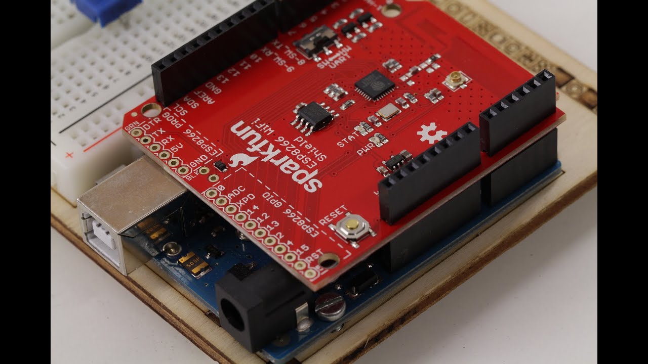
1. Montar nuestra tarjeta ESP8266 sparkfun sobre
nuestro arduino uno
| |
2. Agregar las librerías a nuesto sketch de
ardunio
| |
3. Cambiar nombre y clave dependiendo de la red
que tengamos en nuestro código
| |
PRONTO ESTAREMOS SUBIENDO UN VIDEO COMPLETO PARA EL USO Y LA CONFIGURACION DEL DISPOSITIVO
NUESTRO CODIGO
#include <WiFiServer.h>
#include <Arduino.h>
#include <SoftwareSerial.h>
SoftwareSerial wifilox(8,9);
#include <ESP8266_Simple.h>
/*/ INFORMACION PARA CONECTAR A RED WIFI
#define ESP8266_SSID "TRENDnet810_2.4GHz_A4PO" //NOMBRE RED
#define ESP8266_PASS "clav" //CLAVE de tu red wifi
*/
#define ESP8266_SSID "1il" //NOMBRE RED
#define ESP8266_PASS "12345678" //CLAVE
ESP8266_Simple wifi(8,9); //PIN_TX,PIN_RX //DECLARACION DE OBJETO O TARJETA WIFI
WiFiServer server(80);
// CONFIGURACION INICIAL
void setup()
{ pinMode(13, OUTPUT); //UTILIZAMOS EL PIN 13 PARA INSTALAR ALLI EL LED
Serial.begin(9600); // INICILIZAMOS EN 9600 BAUDIOS PARA PERMITIR LA COMUNICACION EN PANTALLA
Serial.println("Proceso de inicializacion...");
wifi.begin(9600); // INICILIZAMOS EN 9600 BAUDIOS NUESTRA TARJETA WIFI PARA PERMITIR LA COMUNICACION EN PANTALLA
//SINTAXIS DE wifi.setupAsWifiStation (NOMBRE_RED,CLAVE_RED,&DONDE_DESEAMOS MOSTRAR EL MENSAJE QUE REGRESA : OK SIGNIFICA CONEXION REALIZADA )
wifi.setupAsWifiStation(ESP8266_SSID, ESP8266_PASS, &Serial);
Serial.println("Conectando... "); //INSTRUCCION QUE INICIALIZA CONEXION CON RED
// Esta instruccion permite al operador confirmar a si la conexion se realizo de forma exitosa
char ipAddressString[16]; // 16 bytes necesitamos , en esta variable guardamos nuestra IP
wifi.getIPAddress(ipAddressString); // Con la siguiente funcion usamos el objeto -wifi- que es nuestra tarjeta esp8266 y con la funcion getIPAddress guardamos en la variable ipAddressString nuestra ip
//mostramos en pantalla nuestra ip y la red a la cual nos conectamos
Serial.print("La IP actual es: ");
Serial.println(ipAddressString);
Serial.println("Conectado a red : " );
Serial.println(ESP8266_SSID);
Serial.println();
// setWifiMode se utiliza para configurar el modo en el cual usaremos nuestra tarjeta wifi : 1 terminal,2 Punto de acceso osea un mini router wifi,3 ambas
wifi.setWifiMode(1);
/*-----------------------------------------Entramos en la creacion del pequeño servidor que nos permitira la comunicacion cliente - servido.--------------------------------------------------*/
// Aqui declaramos las instrucciones
//usar estos comandos en nuestro navegador para interactuar con el dipositivo sintaxis
// ip del dispositivo/nombre del comando
// 192.168.43.183/led ingresar a esta ip para ver la respuesta
static ESP8266_HttpServerHandler myServerHandlers[] = {
{ PSTR("GET /millis"), httpMillis },
{ PSTR("GET /led"), httpLed },
{ PSTR("GET "), http404 }
};
wifi.startHttpServer(80 , myServerHandlers , sizeof(myServerHandlers) , 25 , &Serial);
wifilox.println("AT+CIPMUX=1");
Serial.println( wifilox.println("AT+CIPMUX=1"));
Serial.println("Listo, conexion exitosa ; comandos disponibles :");
Serial.print(ipAddressString);
Serial.print("/millis");
Serial.println();
Serial.print(ipAddressString);
Serial.print("/led");
Serial.println();
Serial.print(ipAddressString);
Serial.print("/");
}
void loop()
{ wifi.serveHttpRequest();
return;
}//cierra looop
//LA SIGUIENTE FUNCION MUESTRA AL USUARIO EN SU NAVEGADOR MILLISEGUNDOS
unsigned long httpMillis(char *buffer, int bufferLength)
{
// FUNCION IMPORTANTE PARA LIMPIAR LAS INSTRUCCIONES ENTRANTES
memset(buffer,0,bufferLength);
//aqui va el codigo HTML que se aprecia en el navegador al momento que el usuario realiza la peticion
strncpy_P(buffer, PSTR("<h1>Millis</h1><p>The current millis() are: "), bufferLength-strlen(buffer));
ultoa(millis(),buffer+strlen(buffer),10);
strncpy_P(buffer+strlen(buffer), PSTR("</p>"), bufferLength-strlen(buffer));
return ESP8266_HTML | 200; //200 significa OK PARA EL NAVEGADOR
}
// LA SIGUIENTE FUNCION ENCIENDE UN LED
unsigned long httpLed(char *buffer, int bufferLength)
{
static byte ledStatus = 0;
Serial.println("Comando recibido: ip/led");
// -----------------------------INGRESAR EN ESTA PARTE EL CODIGO QUE DESEAMOS REALIZAR EN NUESTRO ARDUINO--------------------------
if(ledStatus)
{
digitalWrite(13, LOW);
ledStatus = 0;
}
else
{
digitalWrite(13, HIGH);
ledStatus = 1;
}
// En esta parte le da a usuario
memset(buffer,0,bufferLength);
strncpy_P(buffer, ledStatus ? PSTR("Pin 13 : ENCENDIDO") : PSTR("Pin 13 : APAGADO"), bufferLength-strlen(buffer));
// And return the type and HTTP response code combined with "|" (bitwise or)
// Valid types are: ESP8266_HTML, ESP8266_TEXT, ESP8266_RAW
// Valid response codes are: any standard HTTP response code (typically, 200 for OK, 404 for not found, and 500 for error)
return ESP8266_TEXT | 200;
}
// LA SIGUIENTE INSTRUCCION SE EJECUTA APENAS EL USUARIO INGRESA A LA IP
unsigned long http404(char *buffer, int bufferLength)
{
memset(buffer, 0, bufferLength);
strcpy_P(buffer, PSTR("<h1>COMANDO VACIOV - PAGINA DE INICIO </h1>\r\n<p>Try <a href=\"/millis\">/millis</a>, and <a href=\"/led\">/led</a></p>"));
return ESP8266_HTML | 404;
}

